The Power Supply


The original plan was to build a classic raw supply. A 650W toroid was providing 2x39Veff @8.4Amps which were rectified by a 35A bridge. Smoothing was provided by two Mallory 50,000uF/60V caps. The result was +/- 53V rails with an internal resistence of about 0.5ohm. Both rails were connected through 10Amp slow blow fuses.
Of course, during development, a lab power supply was used. We would suggest using either a variac or a lab power supply when first setting up the amp.
We were unable to to identify any major issues with such a simple power supply. The only annoyance was the amount of 60Hz odd harmonics that extend well into the KHz range (see here for more details). It is possible that these harmonics are the result of a DC imbalance in the toroid core. Therefore, we were considering other power supply options: a dual mono approach (two 350W toroids, with separate 45Veff secondary windings (each providing for one of the channels, also allowing for the full 200W output power) and (potentially for an even higher power version) a dual SMPS. While the dual mono approach would certainly have a positive impact on the crosstalk performance and also may have an impact on the 60Hz odd harmonics, the SMPS approach has many unknowns, mostly related to the EMI.
The above issues, and the need for other supply voltages to power the auxiliary circuitry, made us decide that a more complex power supply is required. One of the core requirements was that the +/-57V rails (powering the OPS and the front end) should be applied last at power on, after all other supplies are up and running within certain voltage limits, and removed first at power off, This is to avoid any transient conditions at power up which may affect the circuitry bias. The speaker protection circuit is a different story and is discussed here.
The power supply schematic is shown here and is also included in the schematics download archive here. This implementation delivers +/-2.5V (via a +5V LM7805 and a virtual ground generator, the TLE2425), used to power the voltage window dectors, the fan control and the amp soft start circuitry. The +/-12V supplies are powering the protection and clipping circuitry and the fans.
Power sequencing is achieved by interlocking (via a pair of on board 10 amps relays) the +/-57V rails with the +5V and +/-12V supplies. If any of the following conditions occur, the +/-57V rails are not connected (or are disconnected) via the onboard relays:
- The +5V supply is missing
- Any of the +/- 12V supplies are missing, or there is a larger than 2V gap between these voltages (e.g. a +12V and -9.5V condition will disconnect the relays).
- Any of the +/-57V voltages are missing, or there is a larger than 4V gap between these voltages (e.g. a +55V and -50V condition will disconnect the relays).
This logic is implemented using two dual MAX973 low power comparators (in a window detector configuration), OR wired at the output, controlling the power relays. The MAX973 comparators are convenient here only because they contain an on-chip precision voltage reference, otherwise you may decide for an alternative (dual) comparator IC and a 1.2V external reference. For more details, see the MAX973 datasheet.
The MAX973 ICs are 5V devices, so their inputs are protected by diodes. Note also the R54/C47 time constant. This is required for avoiding the +/-57V rails over/under voltage protection to trigger at high output power and low frequencies. Without C47, the power supplies sag (in particular at 4ohm and full 200W output power) may trigger the protection for frequencies under 20Hz.
All resitors in the window discriminators should be 1%.
The CTRL input at the J13 connector is used for implementing the amp soft start standby mode as it will be discussed in the auxiliary circuitry section.
Two Plitron transformers of 300W nominal each (but easily delivering 400W with not more than 6% voltage sag or overheating) delivering 2x45VAC 2x18VAC and 1x8VAC, four 35A rectifying bridges and two power supply boards are required for our dual mono implementation.
D36, D44 and C33 (only 4.7uF or even less!) are separately rectifying and filtering one of the 45VAC inputs (namely the transformer output delivering -57V after filtering). This extra -57V rail is used in the protection circuitry to trigger the load (speakers) disconnect when the power is disconnected from the backpanel switch (or the main fuse blows).
In a dual mono implementation, some of the low power supplies (+5V, +/-12V) may remain unused. You may want to decide for a single power supply board, one 600W transformer (minimum), only two rectifying bridges (or even only one!) and only two 39,000uF caps. Experimentally, we noticed that such an approach is not good for an ultra high performance power amp. The DC imbalance in the toroid core is generating 60Hz odd harmonics (impacting the S/N ratio), the crosstalk performance is poor, the stereo amp wiring becomes difficult to manage (mostly because of the need to handle the stray magnetic field and their impact on the 2nd harmonic distortion). For the ultimate performance, we would stronly recommend the dual mono approach.
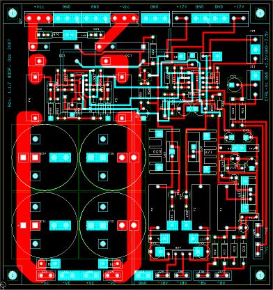
A view of the power supply PCB is shown below (as usual, the top ground plane is removed; click on the image to get a high resolution version). Note the ground split between the power ground and the +/- 12V ground (to avoid a ground loop) and the ground copper pour areas (the blue rectangles) to avoid the default four whisker connection of ground pins to the ground plane. The Gerber files can be downloaded here.


The Ultimate Audio Amp
From Genesis to Revelation
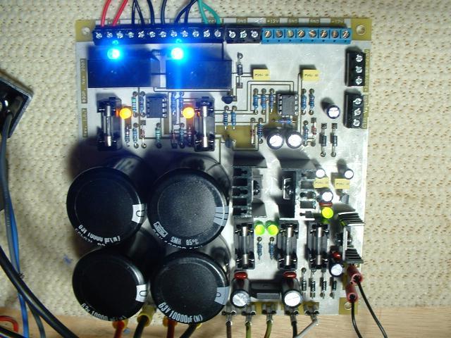
A photo of an assembled power supply board is shown below (click on the image to get the high resolution version). Note the onboard LEDs, used to quickly spot the PS status.
One final note: sequencing the power supplies as described above poses tough power constraints for the resistors in series with the +/-57V rails. While in a regular power supply the filter capacitors are buffering and limiting the power supply dV/dt, sequencing leads to a situation in which the dV/dt is very high. Look at R1 and R72 in the front end schematic. C2 and C29 are initially discharged, so the instantaneous power dissipation in R1 and R2 can easily exceed 100W. Metal film resistors are not designed to withstand such power surges, in fact standard 0.25W Yageo devices were repedeatly blown during testing. The solution is to use here 0.25W or 0.5W carbon composition resistors.