The YAP Front End
Yet Another Poweramp
Another way to skin the cat
In the YAP measurements section we concluded that the OPS has, at 20KHz and 300W into 4ohm, worst case, slightly under 0.1% total distortions, mostly second harmonic. The 3rd harmonic (60KHz) component is about 10dB lower.
This is a good situation; a single pole frequency rolloff is always 6dB/octave, so a Miller type loop gain frequency response (even if the loop gain decreases with the frequency) will, most likely, keep the closed loop harmonic components monotonically decreasing with frequency.
0.1% is 1000ppm, so to reach the distortion levels of the PGP amp we would need some 60dB gain at 40KHz. That's unlikely to happen in any single (MIller) or two pole compensation schema, be it standard TPC or TMC. In a Miller compensated amp, 60dB gain at 40KHz maps to a Unity Loop Gain Frequency (or short, ULGF) of 40MHz. That's way over the transition frequency of the output bipolar devices (30MHz) and that's even before considering any second order effects (high injection level effects, etc...). For a two pole compensation schema, the loop gain at 40KHz could be made, say, 6dB higher than in the Miller compensation, at the same ULGF, but the PGP amp performance is still out of reach. We got a good example of why you need more than a two pole compensation schema, like the Cherry NDFL, to reach 1ppm THD20 while still mantaining decent stability margins. Even if one would dare to push the ULGF to very high values, using MOSFETs in the output stage, ultimately it won't really help; it was already mentioned here that, everything being equal (ULGF, current capability, etc...), a MOSFET output stage will have higher distortions because of the abrupt variation of Cgd when Vgd approaches zero.
But we are not looking in YAP v3.2 after ppm level distortions; a 20-30ppm (0.002%-0.003%) THD20 at 300W into 4 ohm, and a nice monotonic spectra, is considered here already beyond any human detection capability. If you disagree, close this page now, and forever hold your peace!
So, to reach our target, we would need 34dB or more of loop gain at 40KHz. This maps to a ULGF of 2MHz or more, which is already in reach for a two pole compensated front end. Let's see how the YAP v3.2 front end implements this.
For quite some time, I'm using mostly current feedback configurations and YAP v3.2 makes no exception. The YAP v3.2 front end is a combination of an Alexander style opamp input stage and a Common Mode Control Loop (short CMCL) VAS. Let's walk through the front end board level schematic below.
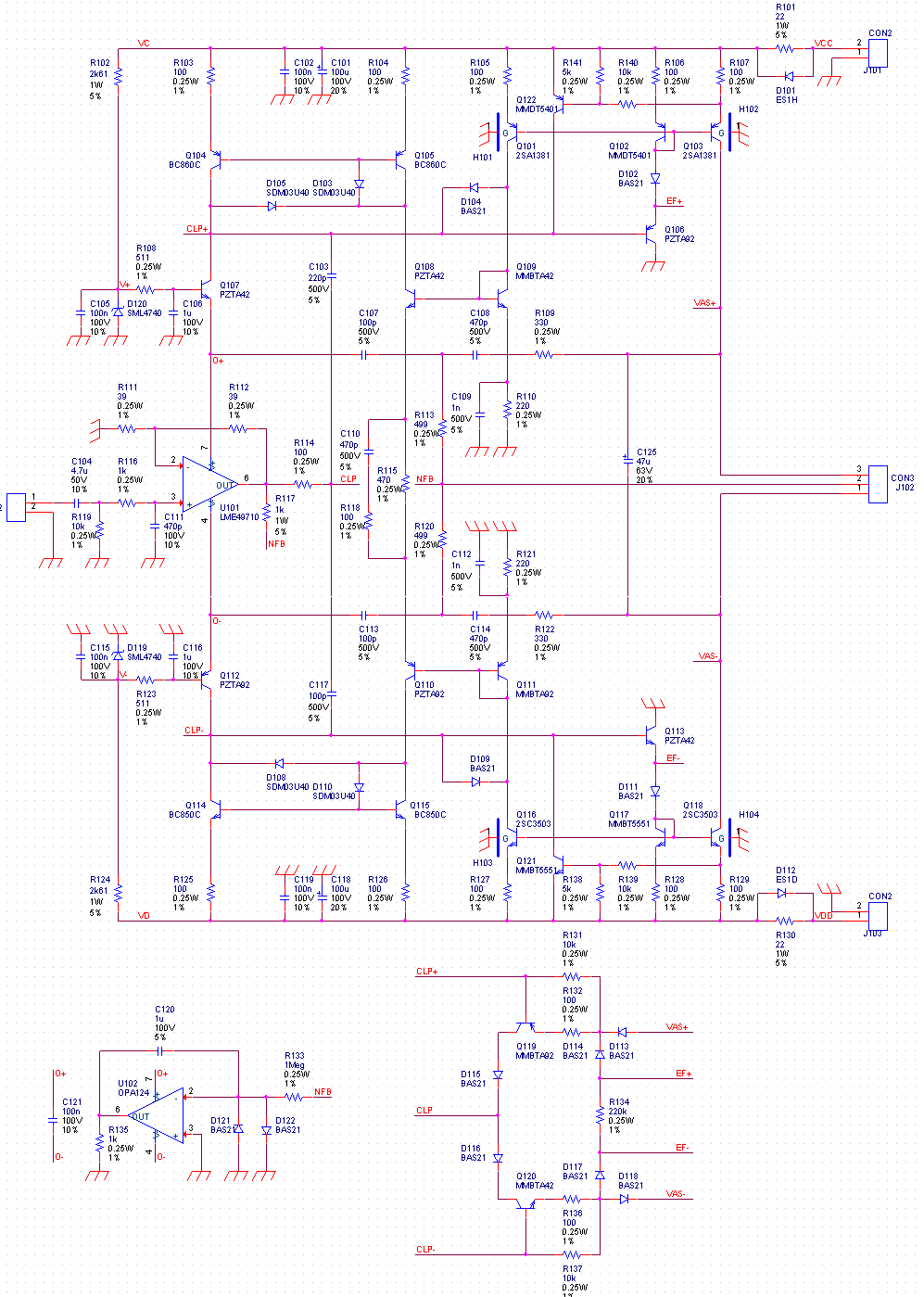
Not much to comment about the input stage; the functional and design details can be found in the Alexander original paper. Q107 and Q112 are loaded by a current mirror, while Q106 and Q103 are standard beta enhancer and degenerated VAS, respectively.
Unfortunately, way to many hobbysts got fried with the Randy Slone's pp. 354 fig. 11.14 design While the symmetry of this amp is certainly sexy, and while the simulation results are promising, this amp has only one "small" problem, it doesn't really work! I dare to call this design the biggest published audio design blunder, ever... It doesn't take much for the skilled to understand why there's a big problem with Randy Slone's circuit: the VAS current is ill defined, and in any practical implementation it will fluctuate from zero to VAS saturation. Therefore, in a fully symmetrical design, the tempting idea to maximize the long pair input stage gain by using current mirror loads needs some sort of bias stabilizing circuitry.
The solution is called Common Mode Control Loop (short CMCL) and it is well known and used in IC designs since the 70's. All we need is a local feedback loop, that reads the VAS current and "adjusts" the current mirrors balance so that the VAS bias current is proportional to the mirrors currents. This is what Q101/Q116 (reads the VAS current) and Q108/Q109 + Q110/Q111 (controlling the current mirrors) are doing. Of course, as any other feedback loop, a little compensation is required. This is accomplished by C109, C110 and C112. The rule of thumb in optimizing here the local loop phase is to keep the time constants equal, so R110*C109=R121*C112=R115*C110. Another zero in the loop gain provided by R118 and the CMCL has enough worst case HF phase margin.
One thing that probably would rise some eyebrows is the simple VAS; no cascode (simple or Hawksford enhanced) is used. Reason is, using the 2SC3503/2SA1381 pair (with very low Cob and Early voltages in the hundreds of volts) in the VAS already minimizes the Early and nonlinear Cob induced distortions. There's virtually no distortion improvement by cascoding a low power device such BC850/BC860 with the same pair.
D102/D11 are adding a little headroom for the Q104/Q114 bias voltage. Q122/Q121 are connected as a standard VAS protection, limiting the VAS and beta enhancer transistors current. While during normal operations the clipping protection offers enough protection (by limiting the gain), during power on/off cycles, a small imbalance in the power supply timing may trigger a potential catastrophic condition. The same transient protection role is assigned to D104 and D109, clamping the bias voltages at safe values and polarity.
D103/D105/D108/D110 are Schottky diodes; the arrangement (a Baker clamp) avoids the potential current mirror saturation under overload conditions.
U102 is the servo; rather than controlling the inverting input of the amp (as in a regular servo), it works by balancing the input stage current mirror loads currents.
Fianlly, the active clipping protection reads the voltage across the beta enhanced VAS. As soon as the voltage exceeds two diodes forward drops (D113 plus the Q119 Ube), a good sign that the amp is clipping, the degenerated Q119 error amplifier kills the VAS gain. D113/D114 are another Baker clamp around the VAS, while R131 and R137 are protecting the transistors against reverse Ube voltages. R134 tries to compensate against the non linear Baker diodes capacitances, by floating the potentials across.
The frequency compensation is Transient Miller Compensation (short: TMC) based. It's not the right time and place to get into a TMC debate, the subject was already beaten to death; enough to know it's a compensation technique derived from the two pole compensation (short: TPC) method and patented in the late '70s. It was eventually analyzed by Baxandall and lately revived by E. Stuart on DIYAudio (which also baptized it as "TMC") and also by Bob Cordell in his latest book. In this thread, it was mathematically proved (and confirmed by simulations) that TMC is exactly equivalent to a standard TPC plus a lead-lag compensation. As such, TMC does not, in any way shape or form, offer any performance improvement over TPC, neither in the loop gain or phase margin departments. It's only a clever way to split the same avalable loop gain across both the OPS and the VAS.
This being said, here's the simulated loop gain and phase of the entire (OPS + front end) YAP v3.2 amp.
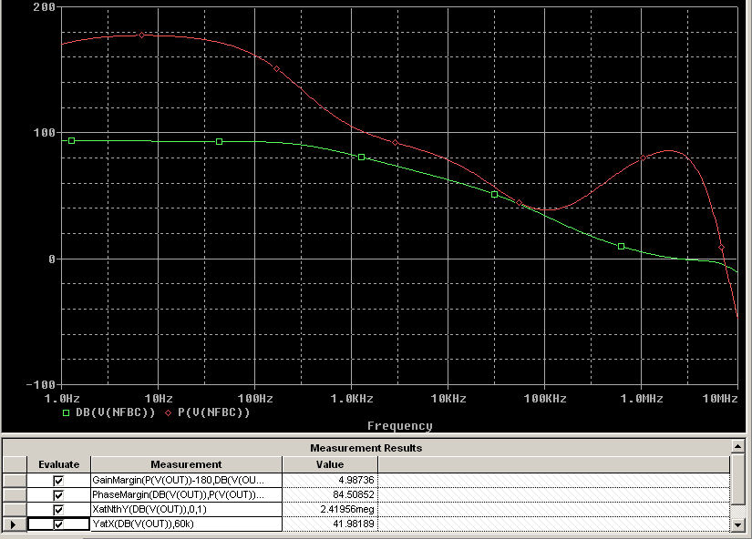
For the purpose of this simulation, both the global and the TMC loops were broken. It is clear that, from a design perspective, ve reached our target. The loop gain at 60KHz is 41dB, while mantaining a consistent phase margin of 84 degrees at the ULGF of 2.4MHz.
Excluding the TMC loop from the loop gain analysis reveals the standard, Miller shaped, gain phase characteristic.
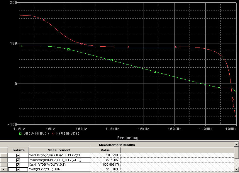
ULGF is a conservative 800KHz, the phase margin approaches 90 degrees, while the loop gain available at 60KHz is now 21.8dB (the balance to 41dB is actrually used to linearize the OPS, so essentially nothing is lost!). There are obvious reserves for the adventurous designer to push up the TMC ULGF and loop gain, and hence further improve the closed loop perfomances, just adjust CCOMP and RCOMP in the simulation!
Finally, due to the very high Miller loop gain, some local frequency compensation is required. This is accomplished by C103=C117=220pF, the Miller loop ULGF is in the 10MHz range. There's enough room to dance here as well!
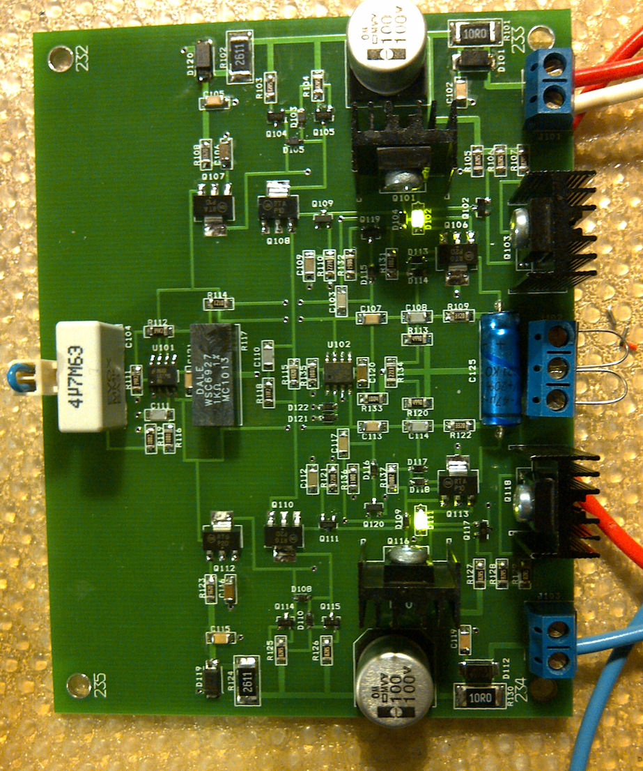
You can download the YAP v3.2 Front End Gerber files. Here's a picture of the assembled front end board.
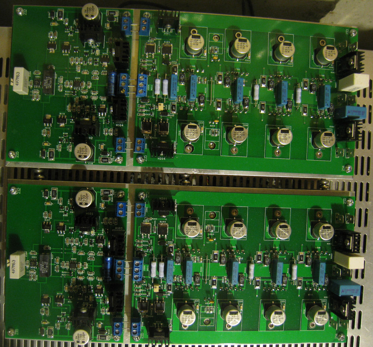
And here's the entire YAP v3.2 amp assembled and ready for testing. The wiring is strictly for static/bias/thermal testing, in the final construction the input stage is fed from directly from the power supply output and the star ground).